Editor’s note: The grounding of the Blanik L-13 fleet has created a number of problems around the world. I found this article interesting; however, this approach has not been approved and is provided here for information and to stimulate discussion. — WE
Note about the author: Francisco Leme Galvão, (urupema@ directnet.com.br) is an aeronautical engineer. He earned an M. S. in aerodynamics at the Instituto Tecnológico de Aeronautica. Francisco worked on the design of the “Regente” and “T-25 Universal” airplanes at S. C. A. NEIVA, and of the “Brasília”, “T-27 Tucano”, “ERJ 170 e 190” airplanes at EMBRAER, and in the structural and architectural design of the “SCD-I”, “SSR-1”, and “SACI” satellites at I.N.P.E. (all in Brazil).
Eng. Francisco Leme Galvão
São José dos Campos SP, Brasil, Feb. 2011
Introduction
The structural design of an aircraft to resist fatigue damage can be done by the use of safe life, fail safe, or both combined criteria (ref. 1).
When the pure safe life criteria is employed, although large safety and scatter factors are usually considered, the operational environment assumed in the computations or in the fatigue tests may greatly differ from the real operational environment, as quoted as being the cause of some recent Blaník L-13 accidents, in which fatigue rupture of root spar and fittings were probably at stake.
Besides the difficulty in accessing the already spent fatigue life of each glider, the Blaník wing root and its fittings design, makes difficult the use of internal reinforcement and detailed latter routine inspections, so that the pure safe life criteria could be kept. Also a fail-safe approach considering internal alternative load paths, although possible, would result in a complex and costly solution.
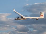
Considering this, the present proposal considers the introduction of wing external struts joining both wings to fuselage, as shown in Fig. 1 in next page, that will act as fail-safe elements and as so, shall be designed to resist only from 80% to 100% of its limit loads (ref. 1).
For positive load factors the introduction of the strut, will result in:
a) A reduction of the bending moments inboard of the strut attachment point, of their associated wing spar caps stresses and of the wing to fuselage attachments loads
b) An additional reduction of tension stresses in the same region, due the compression load component resulting from of the strut reaction.
For negative load factors, although the same reduction effects as in a) above will occur, the tension load component of the strut reaction, will raise the tension stresses instead.
Since usually, the larger part of a wing fatigue damage is done by small load factor increments above and below the unity due to the most frequent, but also small gusts and so mostly positive load factors, and since the limit negative load factors are only 50% of the positive, the net result certainly would be an enhancement in the fatigue life of inboard wings.
Due to the redundant character of the resulting structure, that here on will be referred as a “braced-cantilever wing”, the correct computation of the inboard wing and fittings stresses and their fatigue life, will require a detailed analysis using a finite element model, simulating the inboard wing structure, the strut, and the fuselage structural components affected, as well as the knowledge of the wing aerodynamic and weight load distributions.
This is a task, that besides being outside the scope of the present proposal, considering the huge amount of data required, would be much more viable to be done at the LET Aircraft Industries premises,
Anyway, with the failure of one of the root spar caps, or of one of its root attachments, although the root attachment pins are orientated in the z axis, the remaining wing structure could be considered as being root articulated in the longitudinal x axis and the strut fail safe loads, its design and its effects on the glider performance could be estimated as will be shown.
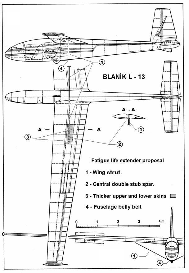
Fig 1 – Strut braced-cantilever wing Blaník 3 View.
Strut Fail Safe Loads
The maximum half wing net load for a load factor nz = 1 is:
Fz nz=1 = (M – mw). g/2 M = glider mass = 500 Kg, mw = wing mass = 150 Kg
g = 9,81 m/s2 Fz nz=1 = 171,7 daN
Assuming for this load a simplified and approximate distribution proportional to the wing chord outside of the wing root and constant over the fuselage, the cantilever wing shear forces and bending moments for nz =1 can be estimated as shown in the Table 1.
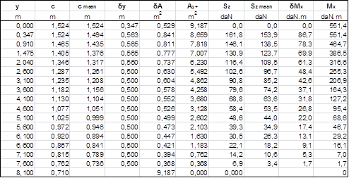
Table 1 – Cantilever wing internal loads for nz =1 load factor.
In a root articulated braced wing, in order to reduce shear loads, the strut center line should intersect the wing spar neutral line at the middle point between the root articulation and the resultant wing load application point y = 0,347 + Mx 0,347 / Sz 0,347 = 3,755 m, that is: y ~ 2,050 m, and the proposed geometry for the braced-cantilever wing is shown in Fig. 2 below.
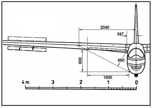
Fig 2 – Strut braced-cantilever wing geometry.
In the case of an upper wing root attachment failure, if the lower attachment is considered to act as a longitudinal articulation, the strut will have an actuating arm a = ~ 0,65 m in relation to it and for the limit negative load factor nz = – 2.5, the strut compression fail safe load, will be:
Sc = – 2,5.Mx y=0,347 / a = – 2121 daN
In the case of a lower wing to fuselage attachment failure, the strut will have an actuating arm a = ~ 0,8 m in relation to the upper fitting, and for the limit positive load factor nz = + 5.0, the strut tension fail safe load will be:
St = 5 . Mx y=0,347
/ a = + 3446 daN
For the strut braced-cantilever wing, the strut limit loads should be computed using a FEM model, as already mentioned, but it is expected that for a rigid root they will be smaller than the above root articulated estimated values, as also indicated by the approximate computation presented in Appendix I, done considering estimated wing stiffness values.
The failed wing attachments loads are then the limit loads to be used in the design of the strut, its attachments to the wing and fuselage, and all other locally affected wing and fuselage structural members such as: wing stub spars, ribs, belly belt, etc. sketched in Fig 3 below.
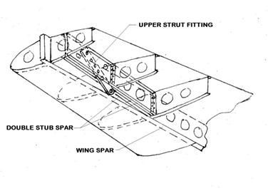
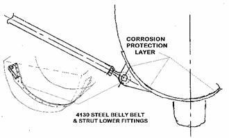
Fig 3 – Hand sketches of strut wing, and fuselage fittings.
Strut Design
Disregarding the possible use of commercial streamlined 4130 or 1025 steel extruded tubes, a simple 1025 steel 3,6 x 1,2 x 0,049 inches elliptic cylinder (l/d =3), can be chosen and its critical buckling load will be: Fcc = Pi2 . E . Is / L2 , where Is is its minimum (major axis) inertia
E = 29000 ksi L = strut length = 66,9 in Is = 0,0753 in4
Fcc = – 4812 lb = – 2140 daN
a value 0,9 % above the upper wing attachment failure, estimated fail safe compression load, and that also will have a yield load Tsy = Fty. As, largely above the tension fail safe load since:
Fty = 145 ksi As = 0,183 in2 Tsy = + 11793 daN
Strut aerodynamic effect estimate
At Blanik´s best L/D speed V = 93 Km/h, the strut Reynolds Number RN = c . V / ν is:
C = 3,6 in ν = 1,30 10E-5 m2/s RN = 1,82E+05
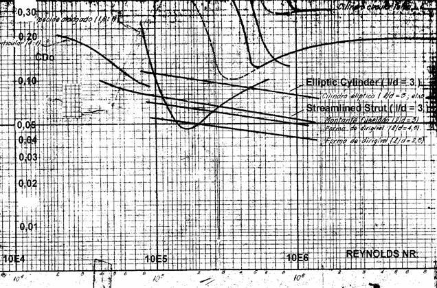
Fig 4 – Drag coefficients of cylinders and bodies (ref. 2).
From Fig 4 above the strut drag coefficient will be Cd = 0,10 and at 93 km/h, and the computed drag of both struts, considering 10 % of interference: Ds = 1,1 . Cd . q . Aso, where q is the dynamic pressure equal to ρ . V2 /2 and Aso is the strut frontal area:
ρ = 1,29 Kg/m2 q = 43,0 daN/m2 Aso = 0,104 m2
Ds = 0,491 daN
At steady flight, the lift L being ~ equal to weight, for M = 500 Kg the glider drag D is:
D = M . g / (L/D) max (L/D) max = 28,2 D = 17,4 daN
The addition of the strut will reduce the max L/D to L / (D + Ds), that is:
(L/D)´max = 27,4
Additional remarks
a -The proposed architectural configuration with the strut normal to glider center line at the wing attachment to fuselage station, although simple to be implemented will result in a small increase of wing torsion moments inboard of the wing strut attachment point.
An alternative would be a strut having the same forward sweep angle of the wing, with the upper strut attached to the wing main spar (no stub spars needed), keeping the lower strut attached at the same fuselage previous point, so that original cantilever wing My torsion and in plane Mz wing bending moments, will not be affected.
b – Another also effective fatigue safe life extender alternative would be to brace the wing with tension stringers instead of struts, avoiding the introduction of tension on the wing for negative load factors. To avoid the string buckling back and forth in turbulence it could be pre-
loaded to a determined tension level, say to its nz = + 2,5 load.
In addition, due to the smaller stringer needed cross section, if a streamlined shape is used, its effect on the glider performance would be smaller than that of the strut, about an 1% reduction on max L/D.
However, although the fatigue failure of the lower wing root attachment, or lower spar cap, that work mostly in compression, would be much less probable than that of the upper ones, and although depending on failure location and type, they could after failed still hold some compression load, this alternative cannot be considered a fully fail safe structure.
References
Ref. 1: Niu, M. C. Y.; “Airframe Structural Design; Hong Kong Conmlit Press, Jan 1999.
Ref. 2: Unknown, ITA AED-16 aerodynamic course notes, ITA, Brasil, 1958
Annex I
Strut and Stringer Braced-cantilever Wing Limit Loads Estimate
The wing Ixx inertia moments that govern wing stiffness in flexion can be estimated by reverse design, assuming a value for the maximum allowable normal stress σm that could have been used in the design of the Blaník wing for its ultimate +7,5 load factor:
Ixx = Mx 7,5g . h / 2 . σm
Using σm = 51,3 ksi (354 MPa), about 90% of the 2024-T4 aluminum Ftu, and “h” computed as 95% of the maximum wing thicknesses, determined from the wing centerline and tip airfoil maximum relative thicknesses of 15% and 12%, the wing Ixx inertias are estimated as shown in table I-1
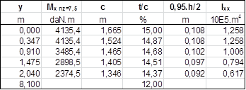
Table I-1 – Estimated wing Ixx inertias inboard of strut attachments.
The cantilever wing z deflections for 1g load factor can then be estimated as shown in Table I-2 by double integration along the span of the corresponding Mx / E. Ixx parameter, with E = 10700 ksi = 73774 MPa for aluminum 2024-T4.
In Table I-3 the same procedure is used to estimate the cantilever wing deflections for a T = 1000 daN tension load applied in the strut and having the same strut direction, and considered applied in the point where this direction intersects the wing neutral line, y = 2,040 m.
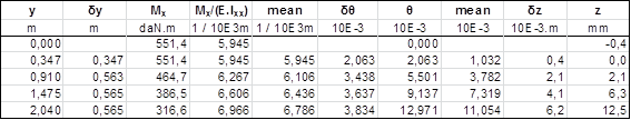
Table I-2 – Cantilever wing deflections for 1 g load factor.
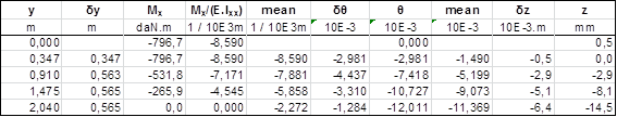
Table I-3 – Cantilever wing deflections for a 1000 daN tension load in the strut direction.
For the same 1000 daN tension load the strut will have an increase in length δL = F . L / E . As
L = 1,70 m E = 200 GPa As = 1,18 cm2
that is, δL = 0,72 mm, with the resulting upper attachment displacement δz = 1,53 mm.
The strut braced-cantilever wing strut load for nz = 1 will be then the load Tnz=1 for which, the cantilever wing deflection plus the upper fitting z displacement corresponding to it would be equal to the cantilever wing deflection for nz = 1, so:
Tnz=1 = 1000 DaN . 12,5 / (14,5 + 1,18) Tnz=1 = 782 daN
and the strut limit loads for the strut braced-cantilever wing (not failed) would be:
Tnz=-2,5 = – 1954 daN Tnz=5 = 3907 daN
These values are smaller, (not so!) as expected, than those computed for the failed wing root attachment conditions, and they would be even lower if the fuselage frame displacements were also taken into consideration, and as a detailed FEM computation will probably confirm.
For a tension stringer of 1025 steel designed to yield with the 3346 daN tension fail safe load, the results for an stringer braced-cantilever wing, computed using the same procedure are:
As = 0,345 cm2 δz = 5,24 mm Tnz=1 = 634 daN
Tnz=-2,5 = – 1586 daN Tnz=5 = 3172 daN
The resulting bending moments for the strut and stringer braced-cantilever wing are compared with the fully cantilever and the braced wing with failed root in the Fig. I-1 below.
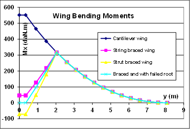
Fig I-1 – Estimated wing bending moments comparison.


4 comments for “A Fail Safe Fatigue Life Extender Proposal for the Blaník L-13”