by Karl Striedieck
Some owners of the Duo Discus have found the wheel brake effectiveness to be less than desired, and the following is a remedy that may help.
The process described deals with a condition where the brake feels “spongy” and there is so much travel in the lever on the master cylinder that actuates the brake that the spoiler handle runs out of rearward travel with little or no wheel brake action. This is usually due to air in the brake line and it must be bled out to regain a solid hydraulic actuation of the slave cylinder on the wheel.
Bear in mind that the wheel brake may seem ineffective even though there is no air in the brake line. This is probably due to the physics of the design. While airborne, the spoilers are easy to actuate and pull back to the point of wheel brake operation, but as speed is lost on the ground the force required to hold the spoiler handle back becomes greater and thus the force going to the master cylinder is reduced.
And there is yet a third condition that can contribute to an ineffective brake, and that is retraction of the pucks (and their brake pads) due to vibration on takeoff or in the air, and, while only a small amount, will use up the entire stroke of the master cylinder lever to reposition the pads against the disc. The obvious solution here is to pump the stick grip a couple times in the landing pattern.
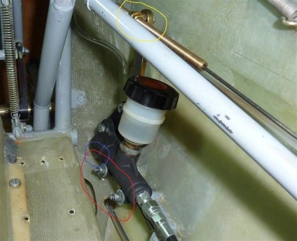
Assuming the problem is air in the brake line, as evidenced by more than an inch of travel measured at the top of the master cylinder actuating arm (see picture “Brake 5” – yellow circle), the hydraulic system must be bled.
Due to the horizontal or even downward loop of the brake line, getting the air out requires special attention. The master cylinder must be positioned well above the slave cylinder to obtain this configuration and the following process involves relocating the master cylinder to ensure this.
However, although not personally attempted, it may be possible to get sufficient height differential by positioning the glider on a substantial slope with the nose and right wing down. Try this first.
Should the more involved (but effective) master cylinder relocation effort be chosen, the steps are as follows:
Stuff a rag below reservoir to catch possible spills and parts.
Empty reservoir with ear syringe.
Unthread actuating rod (“Brake 5 – yellow circle”). Measure adjustment length first.
Remove two 10mm mounting nuts (Brake 5 – red circle).
Slide master cylinder off studs and tilt.
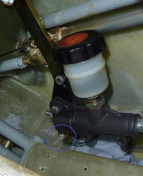
Remove aux (stick grip) brake cables (Brake 4 – blue circle).
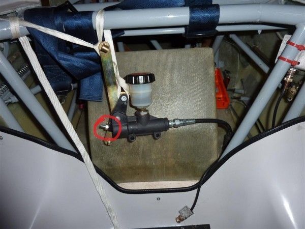
Position master cylinder as shown (Brake 1).
Attach a squirt can of DOT brake fluid (not 5606 as is normally used in aviation) to the nipple on bottom of slave cylinder and open a quarter turn. (Use 12 inches of clear (instrument) tubing on the squirt can and fill it completely before hooking up.)
Pump enough fluid to wash out the bubbles, but avoid overflowing the reservoir. Three half fillings should be sufficient.
If the situation permits, leave the cylinder elevated over night to allow any possible “micro bubbles” to float up.
When finished with the bleeding, actuate the lever a couple times to take up any slack/clearance in the pad-to-disc area. Then give the lever a strong push and it should not move more than an inch after wheel stops rotating. (Use your toe for this.)
The piston adjusting bolt/nut (Brake 1 – red) should be set so that when the lever is actuated there is minimum movement before pressure goes to the slave cylinder. However, there must be some play here to prevent a hydraulic lock caused by the piston covering the orifice to the reservoir. This could result in a locked brake on a hot day. And it would also prevent flow while bleeding.
Reassemble in reverse order. Some swearing may be required to get the cables back on the master cylinder.
With the ship assembled, make sure the adjustment of the actuating sleeve (Brake 5 – yellow) allows full spoiler movement.
