This article was written and submitted to the Café by Eng. MSc. Francisco Leme Galvão (ret.). The original article was published in April, 1977 —Ed.

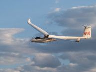
Figure 1. Dream Glider II
You have checked the weather chart, flying gear, food, oxygen supply, etc. The hangar is crowded. However with your unbelievable short span glider, it is very easy to get out and to maneuver between those 15 and 20 meter parked monsters.
Outside the thermals are just puffs of turbulence and everyone is waiting for the conditions to improve in a manner that could [support] those high loaded ships flying. So the tow planes are waiting idle and as result you are free to take off knowing that your old-fashioned 24.5 kg/m^2 wing loading will allow you to stay in the bubbles under those crisp fracto-cumulus drifting with the morning wind, at inversion level.
Turbulence is strong on tow, but your 13 meter small span and a 60 mph towing speed helps you to get up there easily.
One hour later the thermals will really start to show up and everyone will be hurrying to take off, but by this time you have already drifted away climbing in the 0.5 m/s bubbles, flying with your 13 m wing having a good 15% thickness and 4% cambered airfoil. It is like flying an improved 1-26. Low wing loading and quick rolling response is what it is needed to stay inside [and center] the small and turbulent bubbles.
When leaving the bubbles, you crank a lever from the 45° to the 30° marked position and now… miracle! You are flying a 40/1 L/D machine at a very low sink rate.
Your wings have now a 16 meter span and your airfoil becomes a highly cambered 20% thick airfoil. The wing loading has increased to 26 kg/m^2, and so you rapidly fly to the next group of puffs only 2,000 feet above ground leveI losing only 200 feet.
When the weather improves, you keep on alternating between flying straight with your big wings in cloud streets and climbing [in] strong cores with your 45° position low wing loading wing.
Now thermals are really strong and it is time to speed up above 100 mph between them. You crank to a 60° position and… another mirac1e! Now you are flying a hot 9 meter short span hawk with a still higher wing loading of 30 kg/m^2 and stressed to withstand 9g gusts! Your wing has now an only 12% thick low drag and low cambered (3%) airfoil perfectly adapted to the high Reynolds Number and low lift coefficients of high speed flight.
The cumu1us clouds are all around, and so you dash with a low L/D but at tremendous speed between them so covering miles and hours in that post frontal air mass.
Suddenly a big blue hole. Any 15 meter ship pilot would not dare to go through it, but not you. Cranking back to an extreme 25° position allow you to have still bigger wings and so to glide slowly and carefu1ly at 50:1 L/D in the smooth blue air, heading to that cloud street showing up over the horizon.
When getting there, you keep your big 60° wings to climb in the weak sucking air of the afternoon heat, up to the last edge of the now sunset-purpled cloud base. Darkness is coming and you are still gliding on your big wings in the smooth air.
You do not have to worry about off-field landings. Any flat spot will be a good spot. At 1,500 feet. in the semi-darkness some small plowed fields can be spotted at a 30:1 angle.
Downwind before turning, you crank back your wings to the 45° maximum wing area position and the 13 meter span ship comes [in] easily for landing in the plowed field, at 60, 50, 40, 35 mph. Very easy indeed with that trailing edge full span small chord flaperon dropped to 60°.
Before leaving the glider, you crank your wings to a minimum size 15° position, so that your 5 meter span ship could stand any night gale that may try to blow the now 60 kg/m^2 wing loading ship up again into the sky.
You check your map and think, “Really a 1,000 mile flight is now something easy even for gliding beginners.”
Miracle? Dream? No, just reality if the GVG wing concept becomes real.
And what is GVG? Well, GVG is something theoretically feasible and possible if designers could develop a flexible surface and a geodesic articulated wing structure, resulting in a Geodesic Variable Geometry ship.
Geodesic structures have been used in aviation in the past, and one of its most striking examples is the known Wellington bomber designed by the famous British engineer Mr. Wallis and used by England in WWII. This bomber had the property of [continuing to] fly even after severe German flak damage, due to the redundancy provided by its geodesic structure.
Geodesic structures fit easily in double curvature surfaces and for this reason some amateur built fuselages have been made with wooden geodesic elements. Architects and building engineers use geodesic trusses for domes and to create beautiful compound surfaces.
Another important characteristic of geodesic structure is its ability to carry torsion and shear loads without [the] help of any skin, and it is this last characteristic that made me think on the possibility of a pined or articulated geodesic variable geometry wing as shown in the sketches that follow.

Figure 2. Geodesic Variable Geometry (GVD) wing planforms
The wing shown is rectangular for the sake of building simplicity; however, a simple trick can be used to design a tapered geodesic wing with equal central frame elements along the entire span. The same trick can also be used for normal spar/rib structures to obtain tapered wings with the equal upper and lower (split ribs) central ribs along the entire span.
The trick consists in [in generating] the root and tip airfoils from a mid-wing airfoil by displacing its upper and lower contour from, say 10% to 75% of the chord, of a fixed distance to a parallel position, and designing nose and trailing edges to fit the new curves. The resultant wing will have a cylindrical center section and conical leading and trailing edges.

Figure 3. Geodesic Variable Geometry resultant airfoils
Geometrically the process is simple, but aerodynamic knowledge will be needed to develop the root and tip nose and trailing edges to obtain adequate root and tip airfoils that will match the aerodynamic wing desired characteristics. With presently available computer methods this seems to be easily within reach. Figure 4 shows schematically such a wing lay-out for a T. Strand (1) derived central airfoil. However, some problems will challenge the designer of the dream glider described above. One is the weight of the pinned structure and its shape changing actuating mechanism, and another is the needed flexible wing skin.

Figure 4. Tapered wing layout with cylindrical center surfaces
An elastic skin is a possibility; however, the resultant surface will present flat surfaces resulting in a poor high drag, low lift wing. A geometrically variable “honeycomb” could be used to support the elastic skin, reducing the surface distortion to small scale. A simulation of feather or scale-like surface sheet elements [for the] skin is another possibility, but sealing and jamming problems seem to be insurmountable.
Well, this article was written with the objective of stimulating creative designers and with the hope that someone else will achieve a solution. It is possible that hanglider or paraglider designers, who are used to flexible and deployable wings, may find the GVG concept more adequate to their needs than the normal glider community.
Meanwhile we have only to envy the bats, vultures, and gulls for their superbly designed variable geometry (or “morphing”) wings.
———–
Ref 1) T. Strand – Exact Method of Designing Airfoils with given Velocity Distribution – Journal of Aircraft, Vol. 10, November 73.
About the Author
Francisco Leme Galvão, (urupema@ directnet.com.br) is an aeronautical engineer, who earned an M. S. in aerodynamics from the Instituto Tecnológico de Aeronautica. He worked on the design of the “Regente” and “T-25 Universal” airplanes at S. C. A. NEIVA, and on the “Brasília”, “T-27 Tucano”, “ERJ 170 e 190” airplanes at EMBRAER, and on the structural design of the “SCD-I”, “SSR-1”, and “SACI” satellites at I.N.P.E. (all in Brasil).
2 comments for “Dream Glider”