Design Constraints
The design of an open class sailplane from a competition pilot’s viewpoint is relatively simple. Such a glider should have outstanding straight line and thermaling performance, good handling qualities, and a comfortable cockpit. The pilot may also want an engine since outlanding a 28 to 31 meter span ship can often get very interesting as well as putting himself and his placing in the competition at risk. Unfortunately each of these criteria is normally compromised in the end when designing a sailplane for production or, to put it more directly, when the business side of the equation is considered. The market for a pure open class competition sailplane is relatively small for a number of reasons, starting with cost and ending with the effort associated with assembly and handling on the ground. Because of the limited market and the high cost of design and certification, a manufacturer must make compromises that limit the realized racing performance. One of the most significant compromises is to design a wing planform for a single place competition ship that can also be used for a two place sailplane. From a business perspective this makes a lot of sense but from a competition pilot’s viewpoint this is a significant compromise. A 28 to 31 meter two-place sailplane with an engine requires a wing area somewhere in the 16 to 18 square meter range to achieve a reasonable minimum wing loading. Such a large wing area constrains the wing loading range achievable with a maximum takeoff weight of 850 kg that is now enforced in FAI-sanctioned open class competitions. In addition, a wing with this much span and area has a detrimental effect on handling qualities, unless it has a very long tail boom and/or large vertical and horizontal stabilizers. The increase in wetted area from the tail boom and stabilizers increases the parasite drag at high speed and this in turn decreases straight line performance, and the list goes on and on. The point is that small changes in wing area can have significant effects on competition performance.
Both good handling qualities and a reasonably comfortable cockpit are extremely important criteria for maximizing the performance of a sailplane. As we all know, the longer the wing span the slower the roll rate, and the more adverse yaw has to be overcome when trying to roll into that killer thermal. If you are a top open class pilot you learn to compensate for these deficiencies in order to enjoy the increased straight line performance that additional wing span brings. The best of all worlds would be an open class sailplane with the handling qualities of a 15 meter ship. If this could be achieved the pilot would have a definite advantage over his competition in entering and centering a thermal in addition to reducing the fatigue experienced on a long contest flight. Again one of the key parameters for good handling qualities in addition to wing span is wing area. The lower the wing area, the higher the vertical tail volume coefficient for a given wing span, and the higher the tail volume coefficient, the better the handling qualities. So again, wing area is a key player in not only performance but also handling qualities. In terms of cockpit comfort, most production sailplanes are designed to fit all from the smallest to the largest pilots. Klaus Holighaus offered a special “A series” of his popular Discus and Ventus sailplanes with increased performance, but this limited the market for these gliders to pilots of smaller stature. In the open class, the market is so small to start with that the manufacturer must build a cockpit that fits everyone. The larger “fits all” cockpit results in more wetted area and in the end a hit on high speed performance. These are only a few of the compromises that affect the design of a production open class sailplane; a thicker wing for incorporating control systems and water ballast, materials selection, aeroelastic tailoring and cost of manufacturing all add to the list.
The Birth of Concordia
Once the design/build team of the NOC sailplane was formed the question of what to name the project arose. As one can imagine there were many names considered and many discarded. The name Concordia was suggested by Waibel and gained immediate assent from the other members of the team. Concordia is a Latin root word meaning harmony or parallel hearts. The parallel hearts of the team assembled to design this special sailplane would, we hoped, be translated into the harmony of the design itself, and from this, Concordia was born.
Wing Loading
One of the most important criteria for the design of any sailplane is wing loading range. The existing open class production sailplanes have a major performance limitation resulting from a restricted wing loading range. With the open class maximum takeoff weight (MTOW) limit for competition being at 850 kg, the maximum wing loading of current ships in the 25 meter span or above range is about 50 kg/sq meter, which is far too small for today’s open competition, even in moderate weather conditions. The recent Eta and EB 28 sailplane designs both suffer from this same wing loading problem with each having wing areas near 17 square meters. As one can see from Table 1, the ETA minimum and maximum wing loading are the same, not what a competition pilot desires. The EB 28 and EB 29 also have a maximum wing loading below that desired for a competition sailplane. The minimum wing loading of the Eta Biter is good for survival conditions but like the Eta, EB 28, and EB 29, it suffers at high speed from the low wing loading.
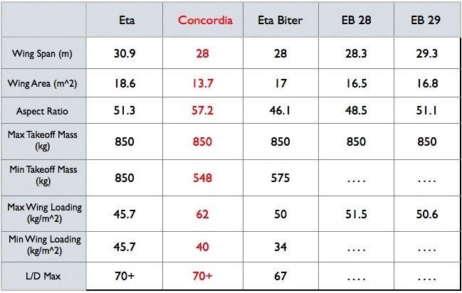 |
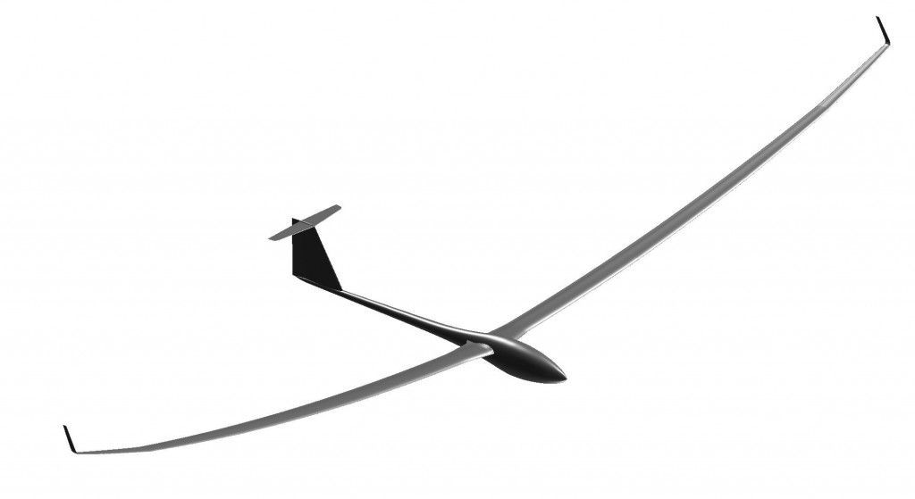
The design goal of Concordia was to have a wing loading range of 40 to 62 kg/sq m with a wing span of 28 meters. With these criteria, the wing area is set by maximum wing loading, which in this case turns out to be 13.7 sq m for a MTOW of 850 kg. A simple calculation shows that the minimum weight corresponding to 40 kg/sq m is then within reach. The designers believed that the minimum weight goal could be achieved by meticulous design and intelligent application of the most advanced composites. As already noted, this small wing area has many advantages ranging from performance to handling qualities. With a 28 meter span, this wing area would also result in an aspect ratio of 57, which would be the highest of any sailplane to date. With an aspect of 57 and a wing loading range of 40 to 62 kg/sq m, both low and high speed performance should be superior to any open class plane presently flying provided: (1) the aerodynamics of the ship are good; and (2) the material properties allow building such a special ship with the required structural characteristics. An initial CAD rendering of Concordia was developed by Dillinger.
Aerodynamics
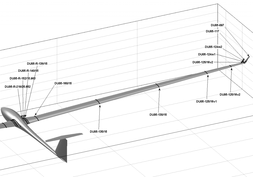
The aerodynamics of Concordia are the brain child of Loek Boermans and Johannes Dillinger. The initial criteria they were provided were: (1) the airfoil must be proven either through wind tunnel test or flight (no new untested theoretical profiles!); (2) the wing fuselage juncture must be designed using 3D modeling and incorporate lessons learned from the success of the ASW27 sailplane; and (3) the fuselage/wing must be optimized for high speed flight (i.e., a lift coefficient of 0.3). With these broad criteria Dillinger at Delft University began the aerodynamic design in 2003 with continuing iterations involving Waibel in Germany and Butler in the USA. To maximize performance at both low and high speeds, Dillinger developed a family of different airfoils ranging from 16% thickness at the root to 12% at the tip.
The thin airfoils were optimum from an aerodynamic standpoint but presented many challenges for Waibel in the overall design and for Butler in the building. The combination of a 28 meter span, thin airfoils, and a very narrow chord imposed by the small wing area made for a very challenging design. For example, where do you find room for water to ballast to 850 kg? All wing control mixing systems would have to be miniaturized to fit within the limited space and the control systems would have to be isolated from the water ballast. Maintaining structural integrity would push the outer limits of what’s possible with the available materials, the consequences of extreme wing bending on aerodynamics/performance would have to be understood and dealt with, and the list goes on. Each of these design problems were addressed and resolved but not without many man-hours and design iterations by Waibel, Butler and Dillinger.
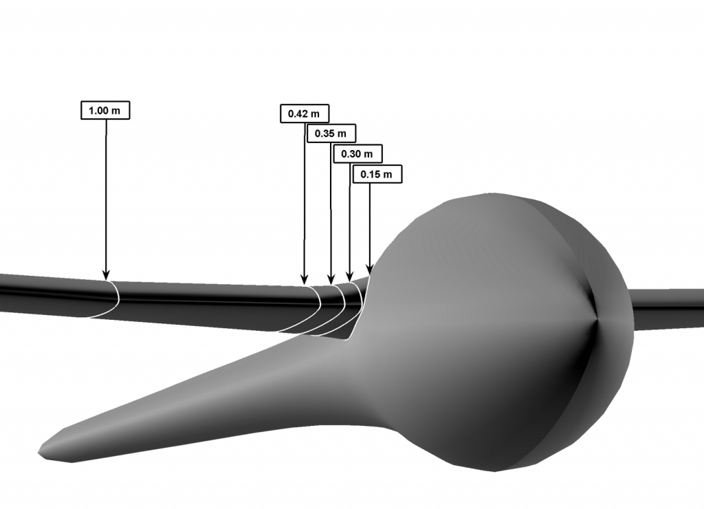
The Concordia wing root juncture was addressed with the 3D panel codes used in designing the successful ASW-27 sailplane. As seen in the preceding figure, a number of airfoils are used in the first meter of wing span along with twist angles to optimize the wing /fuselage flow at high speeds (CL=0.3). Optimizing wing root flow at both low speed (CL=1.2) and high speed is not possible for a fixed wing/fuselage configuration. The primary drag at low speeds occurs from the induced drag of the wing and not from the wing/root junction; therefore, the team decided to optimize flow at high speed where the fuselage and wing junction contribute a large percentage of the total drag.
Figure 4. Computed Flow Streamlines at Low and High Lift Coefficients
Structure and Materials
The ability to ballast Concordia to a MTOW of 850 kg with such a small wing area would require water ballast both forward and aft of the main wing spar. Locating water behind the wing spar brings its own set of challenges, from isolating all control systems, to cg management and potential flutter considerations, definitely not a desirable thing from a production/cost point of view. Structurally speaking, the thinner the wing the more challenging the design from both a strength perspective as well as having sufficient room for control systems. By using the most advanced carbon materials the structural aspects were addressed but the control systems would require major work. Waibel, having designed control mixing systems for the ASW series of sailplanes that incorporated both camber changing and landing flaps, knew all the kinematics required for the Concordia. The problem was to design and build similar control systems for the Concordia but that would fit in a very constricted space. Little did we know all the interference problems that would have to be tackled in the build phase of the project.
Handling
All of the design decisions resulted in a positive spinoff from a handling qualities viewpoint while maximizing high and low speed performance. Two primary non-dimensional parameters are used in designing an open class sailplane for good handling qualities; these are horizontal and vertical tail volume coefficients. These coefficients are for the most part functions of wing area, wing span, tail area, and tail boom length. Without getting into an engineering discussion, the smaller the wing area and span, the better the handling, or the longer the tail boom and larger the tail area, the better the handling qualities. The designer must determine the right mix of these parameters to achieve the desired handling qualities. When one starts with a Concordia wing area of only 13.7 sq m versus the 16 to 18 sq m typical of current open ships, he has a definite advantage. The smaller wing area also means one can now have a shorter tail boom arm and smaller vertical and horizontal stabilizers. For Concordia, a horizontal and vertical tail volume was selected based on previous sailplane designs which had known good handling and stability qualities. The control surfaces and tail boom length for Concordia were sized to give similar handling and stability characteristics. Because of the reduced wing area, Butler and Waibel were able to achieve their handling quality goals with approximately 15% less wetted area than current single place open class ships and 20% less than a two-place open ship, thus permitting superior high speed performance.
Wing Twist
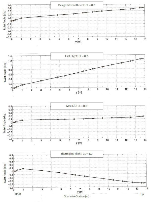
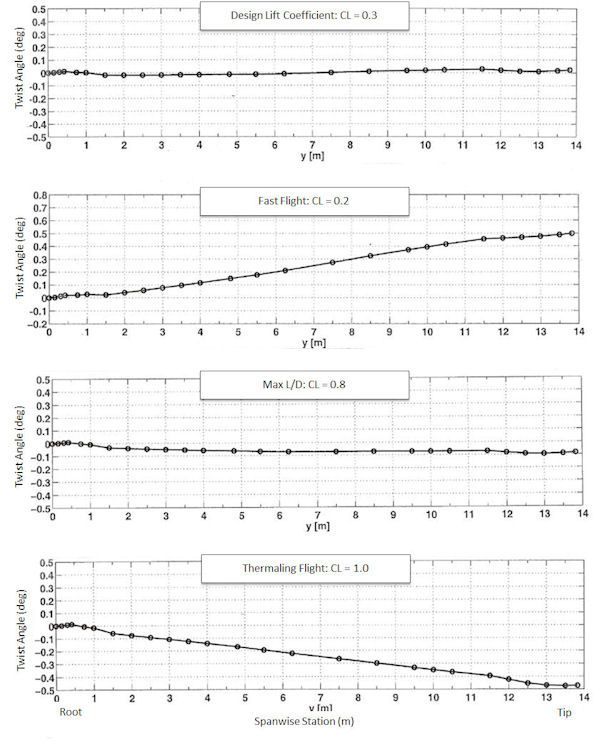
When designing an open class sailplane with a 28 meter span, a thin airfoil, and only 13.7 sq m of wing area, one can expect significant wing bending even in 1g flight. Both NASA and the U.S. defense industry have shown with experimental aircraft such as the X-29 that there exists a coupling between wing bending and wing twist that depends on a number of design parameters ranging from positioning of the wing shear center axis to wing skin lamination orientation and materials used in the wing torsion box. Given the wing bending that was expected in Concordia it became imperative that significant attention be given to the magnitude of wing twist in the outer panels that might develop as the wing flexed up or down. Dillinger saw this potential aeroelastic structural problem as a major challenge to address and decided to continue his studies at Delft University for an additional year to focus on this issue after completing his investigation into Concordia’s aerodynamics. At this time, no other sailplane had been designed with aeroelastic tailoring as a major structural consideration. Dillinger, in close coordination with Delft University structures expert Prof. Z. Gurdal, developed a computer code that he used to design a lamination scheme for the Concordia wing, which will minimize the wing twist that might otherwise accompany wing bending in flight. If conventional lamination were used for the sailplane torsion box and the wing shear center axis were positioned accordingly, the Concordia wing tip would experience a -0.4 degree twist at thermaling speeds (CL=1.0) and a +1.2 deg (up) twist at high speeds (CL=0.2). These data are presented below in Figure 5 along with wing twist at our design lift coefficient of CL=0.3 and at maximum L/D of CL=0.8. The low speed negative twist in thermaling flight would actually be good from a handling qualities viewpoint, but the twist at high speeds and at the design lift coefficient would be unacceptable. By using proper aeroelastic tailoring, the twist at design speed (CL=0.3) and at best L/D (CL=0.8) were eliminated, while retaining a -0.45 deg twist in thermaling flight (CL=1.0) (See Figure 6). We continue to have a small positive twist of 0.5 degrees at high speeds (CL=0.2), but this portion of the flight envelope will only be used when the competition pilot has miscalculated his final glide and elects to burn off altitude in the last few kilometers. The fast flight speed (CL=0.2) for the Concordia with ballast will be in the 255 km/hr range, considerably higher than normal interthermal cruising speeds. Based on Dillinger’s analysis and subsequent wing skin lamination and spar design, we expect that Concordia’s performance at higher speeds will be significantly better than that of existing long wing open class sailplanes with inherent large wing bending.
Performance
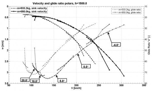
The predicted performance of Concordia is shown in Figure 7. The performance calculation is based on test results of the ASW27 fuselage and tail surface drag scaled for the corresponding areas of Concordia, a mix of computation and wind tunnel data, and wind tunnel data for airfoils used in the Concordia wing design. The predicted performance is very impressive with max L/D in the +70 range and an L/D of 50 at 210 km/hr with full ballast.
More detailed reviews of Concordia’s aerodynamic and structural design have been presented by Boermans, Dillinger and Waibel at venues across Europe and the USA.
For more information. . .
1. Magazine article about the Concordia written by Wolf Herold in 2007
2. J. Dillinger, L.M.M. Boermans
Aerodynamic Design of the Open Class Sailplane Concordia
XXVIII OSTIV Congress, Eskilstuna, Sweden, June 2006
3. J. Dillinger, G. Waibel
Concordia, New Open Class Sailplane
World Gliding Champiosnships 2006, Eskilstuna, Sweden, June 2006



12 comments for “The Design of a Competition Sailplane”